


- info@prototypeshlh.com
- +86-133-9285-9203
- Room 2003, 20th Floor, Xingji Building, Shangde Road, Shajing Street, Bao'an District, Shenzhen
SERVICES

CNC Machining Service
Tight tolerances and finishing capabilities, as fast as 2 days.

Vacuum Casting Service
Production quality parts without the tooling investment.

Sheet Metal Fabrication
Experience the versatility 6 cost efficiency withflexible application options.

Die Casting Service
Create high quality custom mechanicals withprecision and accuracy.

Injection Molding Service
Production-grade steel tooling, as fast as weeks.
Carbon Fiber Manufacturing
Composite materials, such as carbon fiber reinforced plastics are highly versatile and efficient materials.
Popular Services

Injection Molding Service
A faster, easier way to order high-quality injection molded parts that accelerates iteration, testing, and scaled production. Upload your designs for DFM feedback and pricing in 24 hours.

3D Printing Service
Our 3D printing solutions cater to personalised needs with a diverse range of materials and colour options, including SLA, SLS, FDM, Projet, DMLS, and MJF printing services.

Surface Finishing
The easiest way to source your custom parts, with 15+ surface finishing options.

Design Guide
In-depth design guides full of best practices for all of HLH's manufacturing processes.

Case Studies
Success stories from innovativecompanies using HLH.

Blog
lndustry trends, company news andproduct updates.
Featured Posts

3D Printing vs. CNC Machining: Which is Better for Prototyping?
View more →

The Advantages of Projection 3D Printing for Mass Production
View more →

How to Choose Between Aluminum Alloy Casting and CNC Machining
View more →

What is Vacuum Injection Molding? What Type Suitable for Production?
View more →
About Us
Learn about our company, leadership, and mission totransform manufacturing.
Privacy Policy
Applies to all personal information collected through and/or processed in connection.

Contact Us
Our team is on stand by, waiting to assist you.

Videos
A large collection of educational videos and tutorials.

Aerospace & UAV
HLH is your 3D manufacturing partner from prototype to large scale production.

Consumer Products
New Product Introduction Solutions for Consumer Products.

Automotive
New Product Introduction Solutions for Automotive.

Industrial Machinery
The main purpose of industrial prototyping is to take the product from drawings into the real world.

Robotics & Automation
Need some assistance bringing your robotic device or parts from the sketch-board to reality?

Medical Devices
The medical industry needs high quality, dependable and safe parts and products.

Communications
We understand the demands and ever changing landscape of the communications industry.

Product Development
Industrial design and engineering consultancies are some of the most innovate and creative enterprises on the planet.

CNC (Computer Numerical Control) Machining Centers are the backbone of modern precision manufacturing. With a vast array of models available, a clear classification system is essential for engineers, purchasers, and machinists to select the right equipment for a specific job. This article outlines the primary methods for classifying CNC machining centers, providing a structured framework based on industry-standard criteria.
Understanding the differences between CNC machining centers, milling machines, and lathes helps manufacturers choose the right equipment based on part geometry, production efficiency, and machining requirements.
A milling machine is similar to a machining center in terms of basic cutting principles. However, the main difference lies in the level of automation.
Traditional milling machines are not equipped with an Automatic Tool Changer (ATC), which means tools must be changed manually during machining. This increases setup time and limits productivity, especially for complex parts.
In contrast, CNC machining centers are equipped with ATC systems, allowing multiple tools to be used automatically in a single machining cycle. This enables machining centers to perform milling, drilling, tapping, and boring in one setup, making them more suitable for complex parts and batch production.
Machining centers and lathes differ fundamentally in their machining methods.
In machining centers and milling machines, the workpiece is fixed on the table while the cutting tool moves along multiple axes to remove material. This machining mode is ideal for producing prismatic, box-shaped, or flat parts.
A lathe, on the other hand, operates with a rotating workpiece while the cutting tool remains relatively fixed. This makes lathes best suited for machining round or cylindrical parts, such as shafts, bushings, and rings.
The number of axes a machine can simultaneously control is its most fundamental classification, directly determining the complexity of parts it can produce.
3-Axis Machining Centers: The most common and fundamental type.
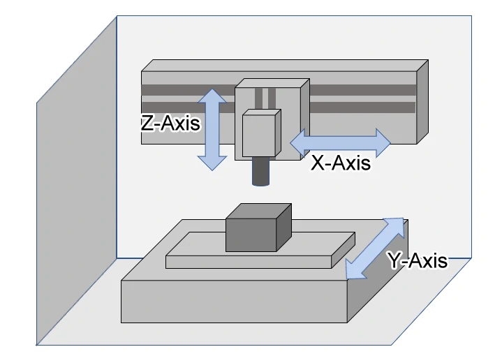
3-Axis Vertical Machining Centers
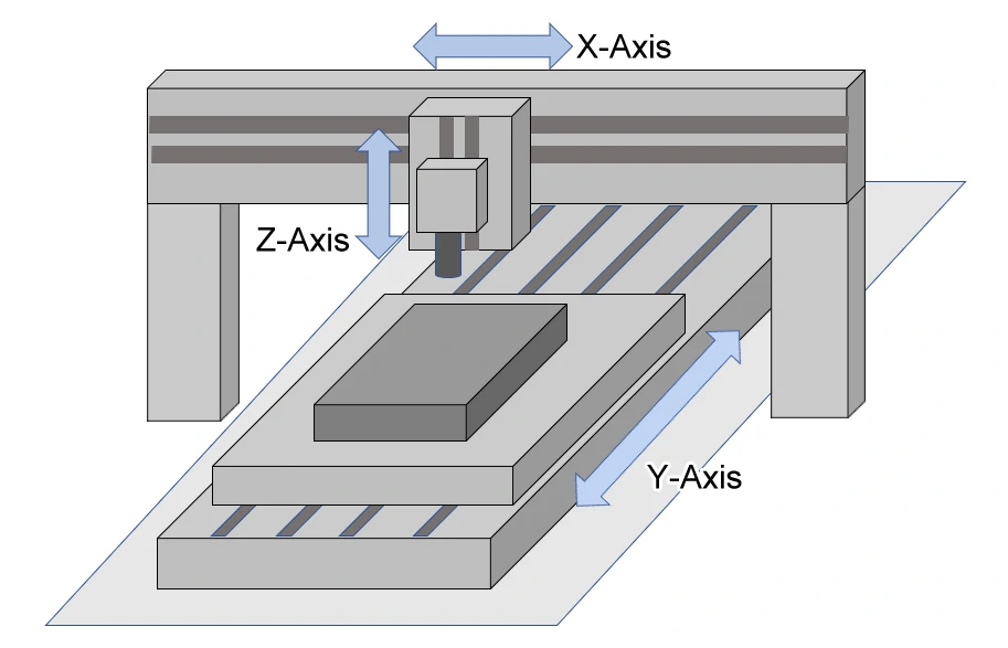
3-Axis Gantry Type Machining Centers
4-Axis Machining Centers: Add a rotational axis to the standard three linear axes.
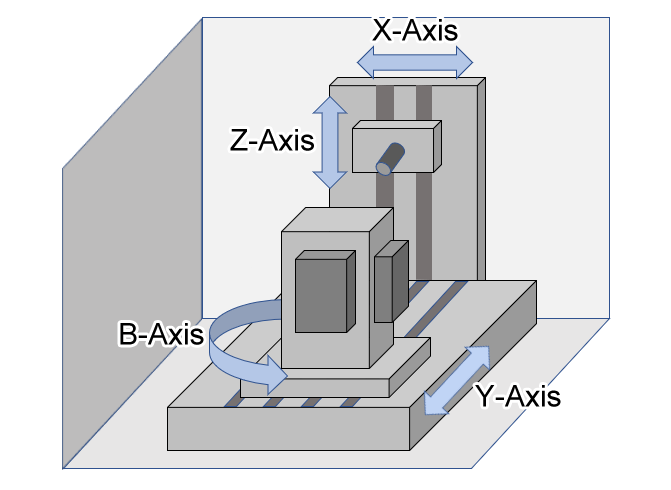
4-Axis Horizontal Machining Centers
5-Axis Machining Centers:The pinnacle of versatility for complex geometries.
| Feature | 3+2 Axis Machining | 5-Axis Simultaneous Machining |
|---|---|---|
| Mode | The two rotary axes position the part, then 3-axis milling occurs. | All five axes move simultaneously and continuously during the cut. |
| Best For | Machining features on multiple sides of a complex part. | Machining intricate, sculpted 3D surfaces with undercuts. |
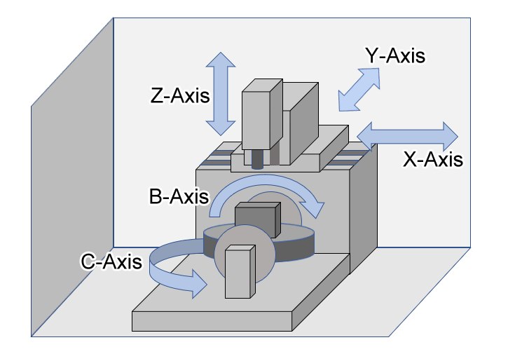
5-Axis Machining Centers
This classification refers to the physical orientation of the machine's cutting spindle relative to the worktable.
Vertical Machining Center (VMC):
· The workpiece is typically mounted on a horizontal table.
· Gravity aids in chip evacuation away from the cutting zone.
· Generally easier to set up and observe the machining process.
· More common for dies, molds, and 2D/2.5D parts.
Horizontal Machining Center (HMC):
· The workpiece is mounted on a vertical indexing pallet (often multiple pallets).
· Chips fall away from the workpiece and tool by gravity, excellent for unattended machining.
· Ideal for boxy parts requiring machining on multiple faces.
· Typically offers higher material removal rates and better stability for heavy cuts.
Applications: Gearboxes, engine blocks, pump housings, and high-volume production.
Universal Machining Center (5-Axis):
The physical construction and scale of the machine determine its rigidity, workspace, and application scope.
· Benchtop/Desktop: Small, for prototyping, education, and micro-machining.
· Standard/Medium Duty: The most common category for general workshop and job shop use.
· Heavy-Duty/Large Format: Designed for massive workpieces, high horsepower, and extreme rigidity (e.g., mining, energy, aerospace components).
Beyond mechanics, the "brain" and purpose define a machine's niche.
· Turning-Milling Centers (Mill-Turn): Integrate a lathe (spindle for rotating the workpiece) and a milling spindle, allowing complete machining of complex rotational parts in one chucking.
· Swiss-Type Lathes (Sliding Headstock): Designed for high-precision, long, slender turned parts. The material bar slides through a guide bushing, and tools machine the part with exceptional accuracy.
· High-Speed Machining Centers (HSM): Optimized for very high spindle speeds (often 20,000+ RPM) and rapid feed rates to machine complex contours in light alloys or graphite with minimal tool pressure.
· EDM (Electrical Discharge Machining) Centers: Use electrical sparks to erode material, capable of machining ultra-hard metals and intricate shapes that are impossible with cutting tools.
Choosing the right CNC machining center requires balancing part geometry, material, tolerance requirements, batch size, and budget. Start by analyzing the part's complexity to determine the necessary axis count. Evaluate the workpiece size and shape to decide between a Vertical or Horizontal orientation. Consider the material removal needs and production volume to select an appropriately sized and rigid structure. Finally, factor in operational preferences and required software integrations when considering the control system.
Understanding these classification methods provides a solid foundation for navigating the vast market of CNC technology and making an informed investment that will drive manufacturing efficiency and capability for years to come.
Contact us today for a free quote on your CNC machining project.
Emali: info@prototypeshlh.com
Phone: +86-133-9285-9203
SERVICES